OPERATION OF VENTILATION SYSTEMS VISUALIZATION

The Goal

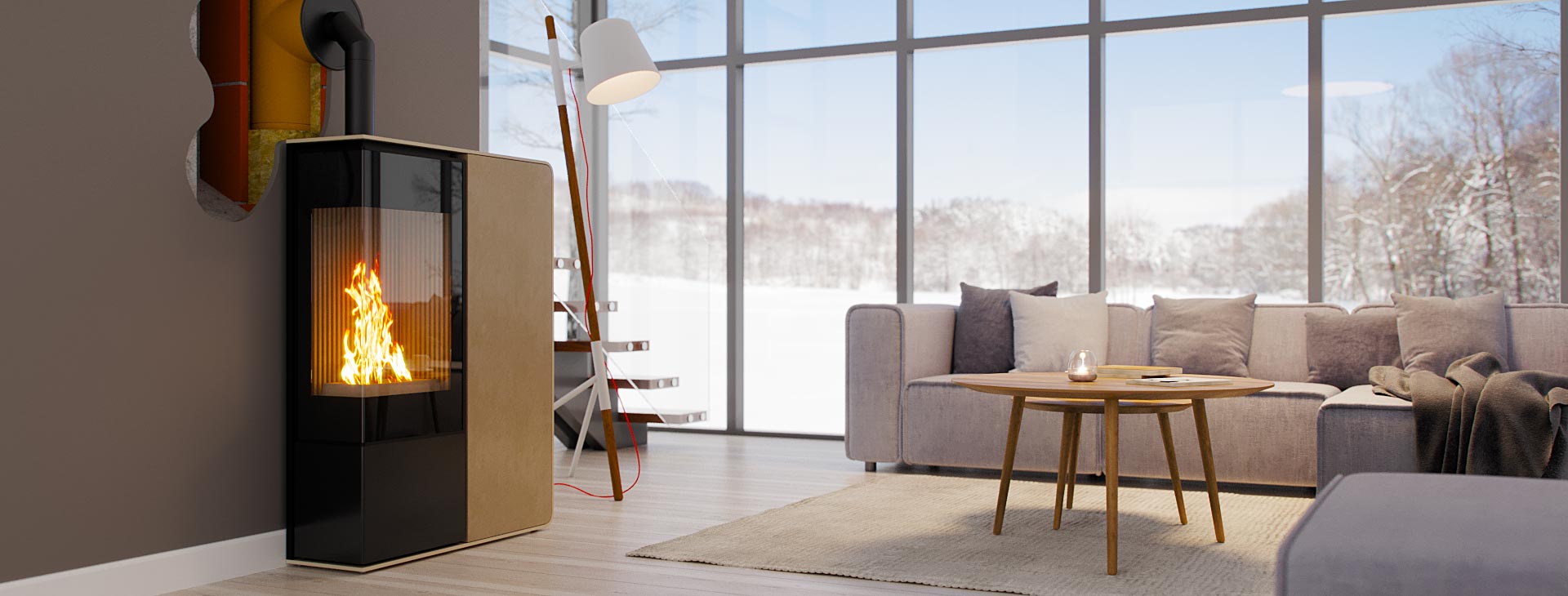
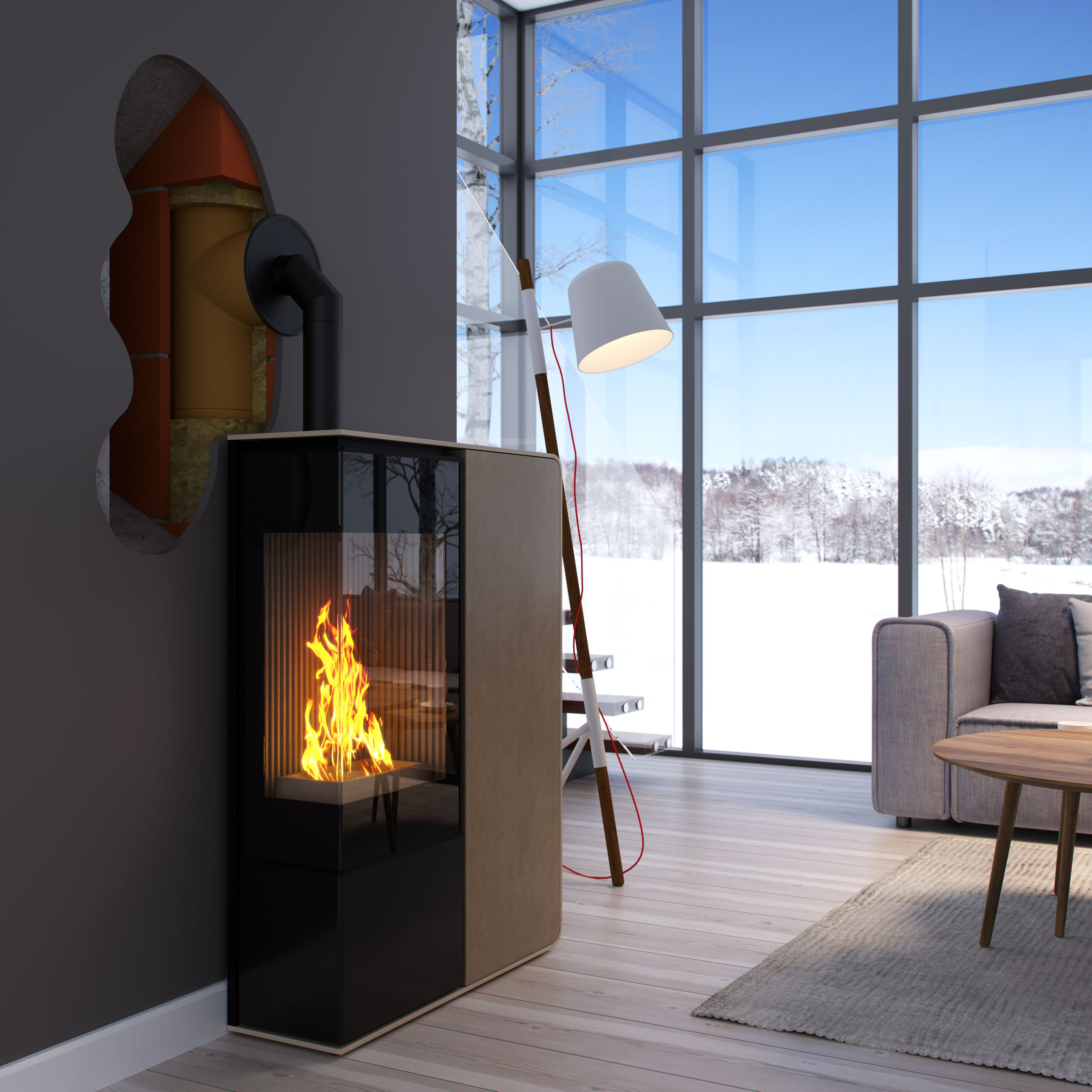
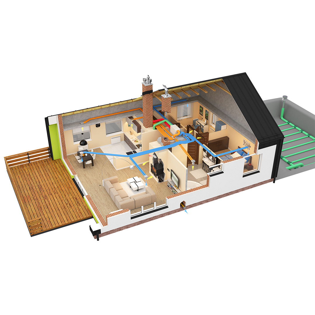
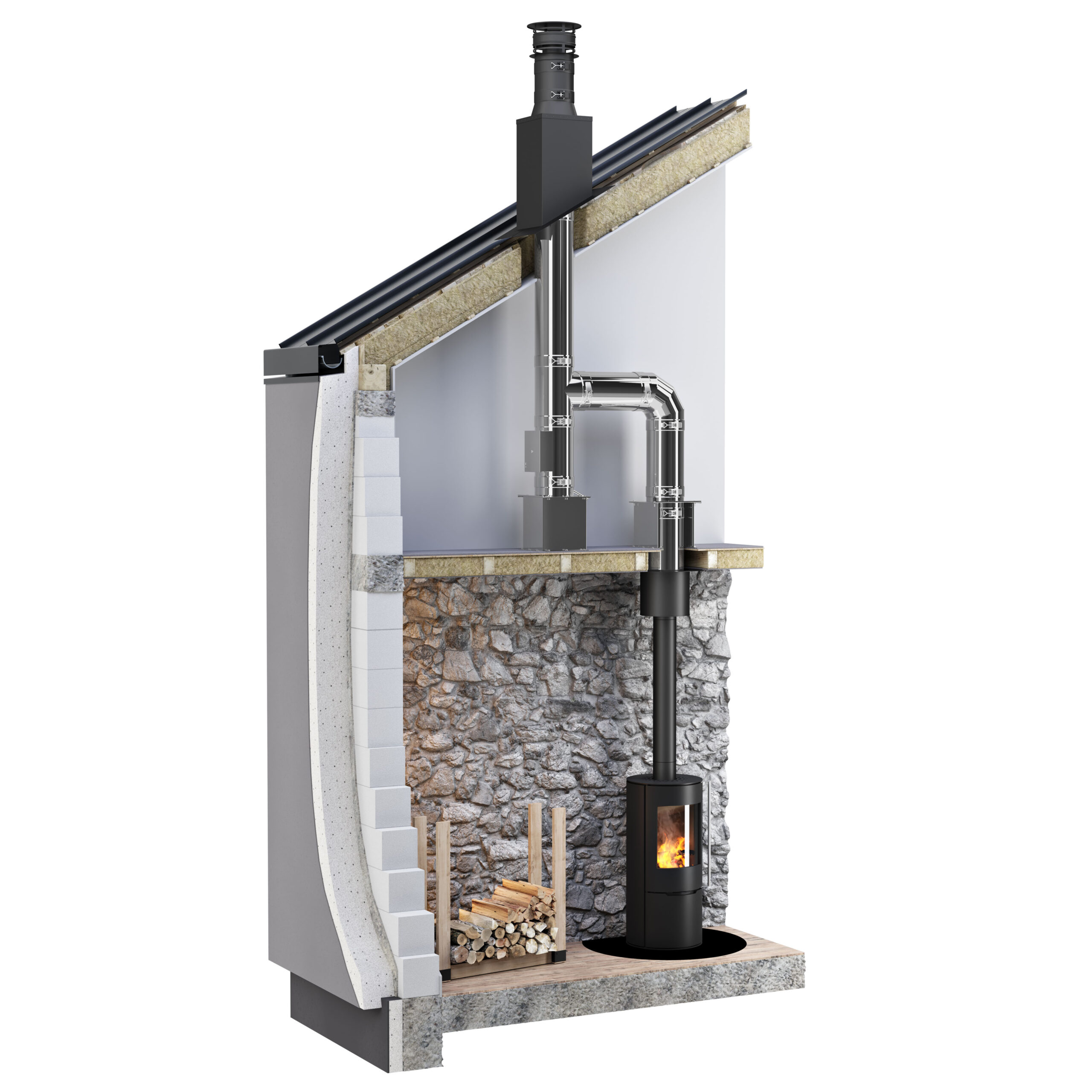
The primary objective of this technical CGI project was to develop a clear, comprehensive visual manual illustrating the operational mechanics and step-by-step installation methodologies of flue chimneys, ventilation stacks, air supply grilles, and hot air distribution systems (DGP) for fireplaces. Explaining multi-layered internal structures and invisible thermal dynamics via standard 2D blueprints or physical photography introduces severe communication friction. The studio was tasked with creating dimensionally perfect digital cutaways and dynamic airflow simulations. The core purpose was to provide manufacturers and engineering firms with versatile visual assets that clarify complex structural installation sequences and thermal fluid behaviors for installers, B2B clients, and distributors.

Technical CGI Engineering

  • Scope – Development of detailed cross-sectional renders and exploded-view 3D visualizations showcasing the mechanics, assembly sequences, and airflow directions of residential HVAC and chimney structures.

  • Inputs – Engineering blueprints, manufacturer component CAD files (.step and .iges formats), step-by-step technical installation manuals, and airflow volume specifications.

  • Geometric Cutaways – Engineered precise, non-destructive Boolean cutaway planes and exploded geometric arrays to reveal internal insulation layers, double-wall clearances, and interlocking pipe joints without compromising original CAD tolerances.

  • Fluid Dynamics and Airflow Vectoring – Utilized custom volumetric particle networks and localized density grids to visually plot hot air distribution paths, fresh air intakes, and exhaust gas flows inside chimney flues.

  • Material Grading and Shaders – Formulated specialized physically-based rendering (PBR) shader networks for galvanized sheet metal, flexible aluminum ducting, porous ceramic insulation wool, and powder-coated ventilation grilles to establish distinct tactile realism.

  • Chronological Assembly Rigging – Built a modular kinematic rigging pipeline allowing for the precise, step-by-step uncoupling and movement of individual assembly layers, providing clear spatial context for mechanical components.

  • Thermal Differentiation Lighting – Employed local emissive light matrices and color-coded interior illumination to separate distinct thermal zones (hot air velocity versus cold intake air) within hidden wall cavities and attic volumes.

The Business Outcome

By translating complex engineering schematics and multi-page assembly manuals into highly readable, non-destructive 3D visualizations, the client fundamentally optimized their technical communication channels. These production-ready digital twins dramatically minimized customer support overheads and reduced field installation errors by providing clear, visual clarity regarding component alignment and connection seals. The resulting visual kit gave the sales and engineering teams a high-performance asset library for B2B product demonstrations, digital e-learning platforms, and interactive installation guides, significantly accelerating product onboarding and market trust.

Project FAQ

How do you ensure that internal mechanical parts remain visually distinct in complex assembly visualizations?

We accomplish this by combining precision geometric cutaways with contrasting PBR material properties. Instead of rendering the assembly as a solid block of metal, our shaders separate the inner flue layer, the insulation blanket, and the outer casing through distinct roughness, metalness, and color profiles. This technical separation ensures that every interlocking joint, clamp, and seal remains structurally legible during close-up camera passes.

What source files are required to simulate accurate installation steps for HVAC components?

To achieve full engineering fidelity, we work directly with manufacturer CAD solid models such as STEP, IGES, or native SolidWorks formats, alongside the actual installation text manuals. This allows our technical artists to replicate the exact chronological mounting sequence, screw threads, locking margins, and bracket fixtures specified by your engineering department, preventing any deviation from real-world functionality.

How is the movement of air or smoke visually represented without looking artificial?

We completely avoid flat 2D graphics or primitive arrow overlays. Airflow and flue gas distribution paths are generated using 3D volumetric particle simulations and dynamic vector fields. This setup computes realistic air turbulence, thermal rise, and velocity drop-offs, providing an intuitive, physically-based representation of hot air distribution and ventilation movement that aligns with actual physics.

Can these instructional 3D renders be adapted into technical animation videos later on?

Yes, the underlying scene architecture is entirely modular and non-destructive. Because the meshes are constructed with clean polygonal topology and integrated rigging layers, the static scenes can be converted into full exploded-view animations, step-by-step technical videos, or interactive web-viewer modules without the need to remodel the components from scratch.

Ready to Accelerate Your Commercial Pre-Sales?

From architectural blueprints to high-fidelity CGI and immersive interactive virtual tours. We engineer visual assets that streamline investor approval loops, maximize property value, and drive conversions.

Discuss Your Project